[MATT Wk 3] Assembly Language Pt. 1
Introduction
Assembly language (ASM) is a low-level programming language, a representation of machine language. It is obtained from the disassembly of machine code.
x86 Architecture Terminologies
CPU and its Components
- CPU: The brain of the computer, executes instructions.
- Registers: Small, high-speed storage locations in the CPU. Stores data and addresses temporarily during execution.
- ALU (Arithmetic Logic Unit): Performs arithmetic (+, -, x, etc.) and logical operations on data (AND, OR, NOT, etc.).
- Control Unit: Fetches instructions from memory, decodes them, and controls the execution of the instructions by coordinating the other components of the CPU.
- Main Memory (RAM): Stores data and instructions for the CPU to access and execute. Provides temporary storage for programs and data.
- I/O Devices: Allow data and instructions to be transferred between CPU and external devices.
Flow of Execution:
- CPU fetches instructions and data from RAM.
- ALU performs operations on the data with registers
- Results are stored back in RAM / output devices.
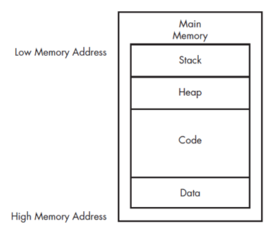
RAM and its Components
- Stack: Region of memory for storing temporary data (e.g., func calls, local vars, return addr, etc.). LIFO structure.
- Heap: Region of memory for dynamic memory allocation, managed by the OS/program. Stores data and objects that are created and destroyed during execution.
- Code: Holds machine code instructions for the program.
- Data: Stores global and static variables used by the program.
The order of these sections may vary depending on the OS, compiler, and program due to memory management strategies.
Assembly Instructions
Syntax
Instruction Format:
| Mnemonic | Destination Operand | Source Operand | |
|---|---|---|---|
| Definition | Operation to be performed E.g., mov, add, sub |
Destination register/memory location where the result is stored | Source register/memory location where the value is read from |
| Example | mov |
eax |
0x42 |
Each instruction corresponds to opcodes, which are the machine code representation of the instruction.
| Instruction | Opcode |
|---|---|
mov ecx |
B9 |
0x42 |
42 00 00 00 |
x86 architecture uses little-endian format (LSB stored first). However, during network communication, big-endian (MSB stored first) is used.
Conversion Examples:
0x42->42 00 00 00(little-endian) ->00 00 00 42(big-endian)0x0100007F(little-endian) ->0x0100007F(big-endian)
Operand Types
-
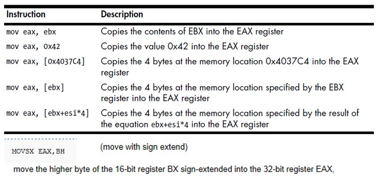
Immediate Operands: Constant value, e.g.,
0x42.E.g.:
mov eax, 0x42 ; Move 0x42 into eax add eax, 0x10 ; Add 0x10 to eax sub eax, 0x5 ; Subtract 0x5 from eax - Register Operands: Data stored in a CPU register (e.g.,
%eaxdenotes theeaxregister). More info in the next section. - Opcode Operands: Machine code representation of the instruction (e.g.,
B9) - Memory Address Operands: Specific location in memory denoted by register, value or equation between brackets (E.g.:
[eax]).
Registers
- Register
- Small, high-speed data storage locations in the CPU for temporary storage and manipulation of data.
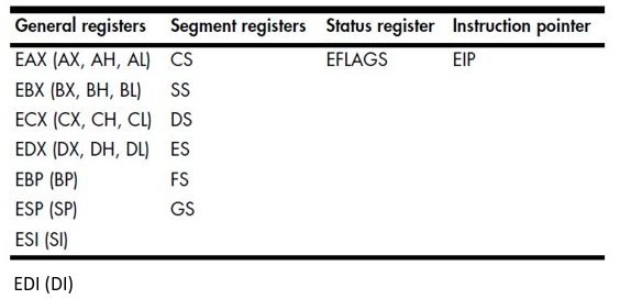
Types of Registers:
- General Register: Used by CPU to perform arithmetic, logical, etc. operations during execution
- Segment Register: Track memory sections (e.g., code, data, stack)
- Status Flags: Makes decisions based on the result of operations (e.g., zero flag, carry flag)
- Instruction Pointer (IP): Stores address of the next instruction to be executed
General Purpose Registers:
Some instructions use specific registers by definition
- EDX: Division
- EAX: Multiplication, Holding return value for function call
- ESP, EBP: Function call/return
- ESI, EDI and ECX: Used in repeat instructions
- ESI, EDI: Store memory addresses
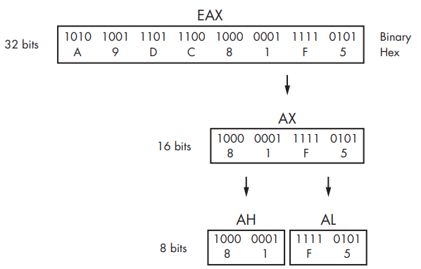
Referencing Registers
- E[]X references 32 bits
- []X references 16 bits
- []L references the lower 8 bits of the []X
- []H references the upper 8 bits
There is no direct way to reference the upper 16 bits as it is unnecessary. (Ref)
Status Register
- EFLAGS
- 32-bit register that stores the status flags.
- Flags that are set based on the result of an operation. Used to make decisions in the program.
- Each bit is a flag that is set to 0 (clear) or 1 (set).
| Flag | Description / Use Cases |
|---|---|
| Zero Flag (ZF) | Set when result of an operation is 0 |
| Carry Flag (CF) | Set when there is a carry out of the most significant bit. E.g.: Overflow of unsigned integer addition |
| Sign Flag (SF) | Set when the result of an operation is negative or when MSB is set |
| Trap Flag (TF) | Used for debugging, CPU will single step |
| Parity Flag (PF) | Indicates if the LSB of the result is even (PF = 1) or odd (PF = 0) |
Status flags just indicate various conditions that relate to the result of an operation.
For instance, the CF indicates if a carry/borrow operation occurred, but does NOT store the actual value of the carry/borrow.
An example of the use of the CF when adding two values:
11111111(255)
00000001(1)
—————–
00000000(0) with a carry of 1 (true)
Instruction Pointer (IP)
- Stores the memory address of the next instruction to be executed.
- EIP (Extended Instruction Pointer) is used in 32-bit mode.
- Attackers can manipulate the IP to redirect the flow of execution to malicious code.
Data Allocation
| Directive | Size | Example | Description |
|---|---|---|---|
| DB (Define Byte) | 1 byte | var DB 64 | Define a byte referred to as location var containing the value 64 |
| DW (Define Word) | 2 bytes | var2 DW ? | Defines a 2-byte uninitialized value referred to as location var2 |
| DD (Define Doubleword) | 4 bytes | DD 10 | Defines 4-byte, containing the value 10. It’s location is var2 + 2 bytes (location is saved relative to the previous variable) |
| DQ (Define Quadword) | 8 bytes | X DQ 100 | Defines 8-byte, referred to as location X containing the value 100 |
| DT (Define Ten Bytes) | 10 bytes | val DT 12345 | Defines 10-byte variable referred to as location val containing the value 12345 |
The
?symbol is used to denote an uninitialized variable (something like an empty container).
It is used to reserve memory space for a variable without assigning a value to it.
When defining variables, you are essentially reserving memory space for it.
If you allocate an 8-byte variable, for instance, to the value100, it will be stored as64 00 00 00 00 00 00 00in memory (or 0x64).
Multiple Definitions / Expression Definition
-
Defining multiple variables at once
var1 DB 1, 2, 3, 4, 5 ; Defines a series of 5 bytes. ; var1 now acts as a label for the list of bytes. -
Defining a string
msg DB 'Hello', 0 ; Defines a string of characters, terminated by a null byte. -
Defining an expression
size equ 50 * 2
; Defines an expression, size, which is equated during assembly
Signed vs Unsigned Variables
- Unsigned variables: Only positive values (0 and above)
- E.g.,
DB 255is the maximum value for an 8-bit unsigned variable.
- E.g.,
- Signed variables: Can be positive or negative
- E.g.,
DB 128to+127is the range for an 8-bit signed variable.
- E.g.,
Reference
Data Allocation Directives in Asm vs C
| Asm Directive | C Equivalent |
|---|---|
| DB | char |
| DW | int, unsigned int |
| DD | long, float |
| DQ | double |
| DT | internal intermediate float value |
Assembly Program Structure
The order of the sections are not strictly fixed, but there is a general structure that is followed.
General Structure
.const          ; Defines read-only values / strings

.stack          ; Defines stack segment (memory for storing temp data, func calls, etc.).

.data           ; Defines initialised data that are modifiable (rw)

.code / .text   ; Contains executable code / instructions
_main PROC      ; Entry pt of he program. PROC indicates start of procedure (function)
    ; Code      ; Note: Main func is in the .code/.text section, they are not two separate sections!
    ret         ; Return from the main function
_main ENDP      ; End of the _main procedure
END _main       ; End of [entry point]
Assembly Instructions
Data Movement
- Move Instruction (MOV)
- Copies data from source to destination (i.e. instruction for reading and writing to memory).
Syntax:mov destination, source
Load Effective Address (LEA)
- Load Effective Address (LEA)
- Used to load/calculate the memory address of a variable and store it in a register.
Syntax:lea destination, source
| Instruction | Description |
|---|---|
lea ax, [bx] |
Loads address of bx into ax register. |
lea bx, [bx+3] |
Stores the address that points to a location 3 bytes ahead of the originalbx into bx. |
lea ecx, [0 + 4*eax + eax] |
Multiplies the value in eax by 5 and stores it in ecx. |
LEA does not load the data stored at the memory address into the register, but rather it loads the address itself!
Arithmetic Operations
- Simple Operations
- Syntax:
op, destination, source
| Instruction Examples | Description |
|---|---|
add eax, ebx |
Adds EBX to EAX and stores the result in EAX. |
sub eax, 0x10 |
Subtracts 0x10 from EAX. |
inc edx |
Increments the value in EDX by 1. |
dec ecx |
Decrements the value in ECX by 1. |
Multiplication and Division
- Requires the use of specific registers!
mulanddivoperate on unsigned integers only.
Multiplication
mulimplicitly useseaxas the destination register.- The processor knows to take in the value in
eaxand multiply it by the source operand. - Example:
mov ax, 10    ; Move 10 into ax, i.e. AX=10
mov bx, 3     ; Move 3 into bx, i.e. BX=3
mul bx        ; AX = AX * BX = 10 * 3 = 30
Division
divimplicitly usesedx:eax;eaxstores the quotient,edxstores the remainder.- Example:
mov eax, 10   ; Move 10 into eax
mov ebx, 3    ; Move 3 into ebx
div ebx       ; EAX = EAX / EBX = 10 / 3 = 3 (quotient)
              ; EDX = 1 (remainder)
Logical Operations
| Instructions | Description/Example |
|---|---|
xor eax, eax |
Clears the value in eax |
or eax, 0x10 |
Bitwise OR with 0x10 |
not eax |
Bitwise NOT of eax; inverts all bits in eax |
and eax, 0x10 |
Bitwise AND with 0x10If both bits are 1, result is 1. Otherwise, result is 0. |
shl eax, 1 |
Shift left by x number of bits. Vacant positions are filled with zeros, shifted out bits are discarded. E.g.: mov eax, 1 shl eax, 1 0001 (1) -> 0010 (2) |
shr eax, 1 |
Shift right by x number of bits |
ror eax, 1 |
Rotates bits right by x number of bits. Bits shifted out are circularly inserted back into the leftmost positions. |
The difference between
shiftandrotateis that shift discards the bits shifted out and fills vacant positions with zeros, while rotate inserts the bits shifted out back, meaning no bits are lost.
NOP / INT Instructions
- NOP
- No operation. Used for padding, debugging, etc.
Syntax:nop- OPCode:
0x90 - Attackers can use this for buffer overflow attacks.
- OPCode:
- INT
- Software interrupt. Used to invoke a software interrupt handler.
Syntax:int nnis the interrupt number.- E.g.,
int 21Hinvokes the DOS interrupt handler.


